The Tape Design of Connectors
As the quality of connector packaging continues to improve, the packaging requirements for connectors become more and more stringent. Tray packaging, tube packaging, and tape packaging have gradually replaced simple PE bag packaging. Among them, tape packaging has become the first choice for SMT series connectors. The tape packaging can not only protect the connector from being deformed by external force, but also realizes the automatic feeding of the connectors. So, what are the problems that need special attention in the design of the carrier tape? Here are some examples for analysis.
1. How to avoid the deformation of the weld tab
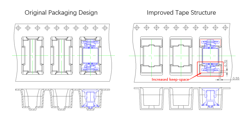
As shown in the figure below, the design of the first packaging method on the left can be used normally on ordinary connector packaging. However, after the vibration and shock caused during transportation, the weld tab of the connector could become skewed, resulting in problems such as missing solder when connectors are installed on the board. After improvement and verification, modification is made as shown on the right side of the figure below. After the improvement, the keep-space between the carrier tape and the weld tab is increased by more than 0.5 mm in all directions, so that the product quality can be guaranteed when the connector is loaded into the carrier tape and when the customer takes out the carrier tape for use.
As shown in the figure below, the design of the first packaging method on the left can be used normally on ordinary connector packaging. However, after the vibration and shock caused during transportation, the weld tab of the connector could become skewed, resulting in problems such as missing solder when connectors are installed on the board. After improvement and verification, modification is made as shown on the right side of the figure below. After the improvement, the keep-space between the carrier tape and the weld tab is increased by more than 0.5 mm in all directions, so that the product quality can be guaranteed when the connector is loaded into the carrier tape and when the customer takes out the carrier tape for use.

2. The connector is tilted inside the carrier tape, resulting in abnormal suction.
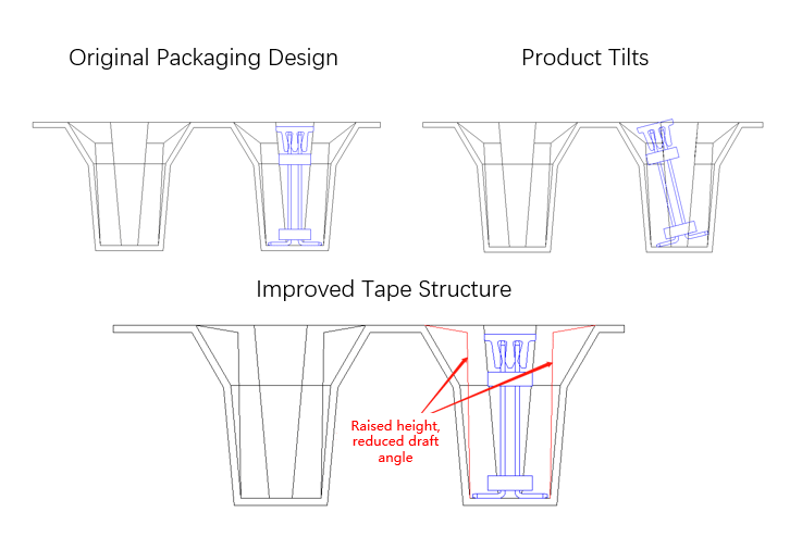
The original design on the left side of the picture (shown below) is a conventional design. It is difficult to find problems before mass production. However, after shipment, sometimes customers come to realize that the products are tilted. After simulation, it is confirmed that there is a small probability of this happening. Generally, tearing off the upper belt bring the product back to its original position. However, after improvement and verification by heightening the structure of the carrier tape, reducing the angle under the premise of meeting the production requirements, and reducing the swing space of the connector in the carrier tape, the connector is then completely prevented from being tilted.
The original design on the left side of the picture (shown below) is a conventional design. It is difficult to find problems before mass production. However, after shipment, sometimes customers come to realize that the products are tilted. After simulation, it is confirmed that there is a small probability of this happening. Generally, tearing off the upper belt bring the product back to its original position. However, after improvement and verification by heightening the structure of the carrier tape, reducing the angle under the premise of meeting the production requirements, and reducing the swing space of the connector in the carrier tape, the connector is then completely prevented from being tilted.

3. The connector climbs up the carrier tape plane.
After shipment, some customers reported that sometimes the connector climbs up the carrier tape plane. This happens rarely, but could cause issues if it were to occur. In order to avoid this issue, the product must be long enough. This problem occurs when, after the upper belt is sealed, the middle position cannot hold down the product CAP due to its elastics. In this situation, the carrier tape will rotate during the winding process, and the connector will rush forward. After one turn, the upper belt will be tightened again, pressing the product CAP so that it cannot be corrected. To improve on the original design, the limit of the plastic within the carrier tape structure is adjusted to a smaller size, and the previous limit terminal is changed to limit the plastic and terminal. The terminal can now climb the slope but the plastic cannot, because the upper belt on both sides of the connector is tightly attached to the carrier tape. In the end, the belt can effectively hold down the connector.
After shipment, some customers reported that sometimes the connector climbs up the carrier tape plane. This happens rarely, but could cause issues if it were to occur. In order to avoid this issue, the product must be long enough. This problem occurs when, after the upper belt is sealed, the middle position cannot hold down the product CAP due to its elastics. In this situation, the carrier tape will rotate during the winding process, and the connector will rush forward. After one turn, the upper belt will be tightened again, pressing the product CAP so that it cannot be corrected. To improve on the original design, the limit of the plastic within the carrier tape structure is adjusted to a smaller size, and the previous limit terminal is changed to limit the plastic and terminal. The terminal can now climb the slope but the plastic cannot, because the upper belt on both sides of the connector is tightly attached to the carrier tape. In the end, the belt can effectively hold down the connector.


